Deconstructing CAD Trees Before Generating Toolpaths
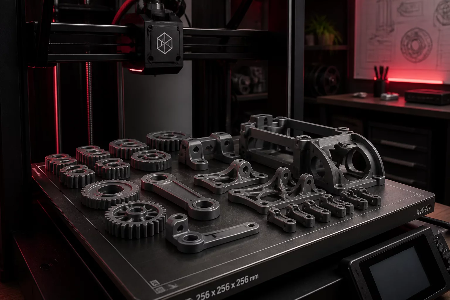
Exporting an entire 18-part parametric model directly into a single slicer window inevitably creates an unmanageable print bed. When parts are arranged purely by geometric tessellation or software auto-nesting, the resulting build plates disregard physical fastener access, sub-assembly milestones, and post-processing dependencies. Operators find themselves waiting twelve hours for an outer cosmetic bezel to finish while internal core chassis parts sit completed but untestable because missing intermediate brackets remain trapped inside an incomplete third plate.
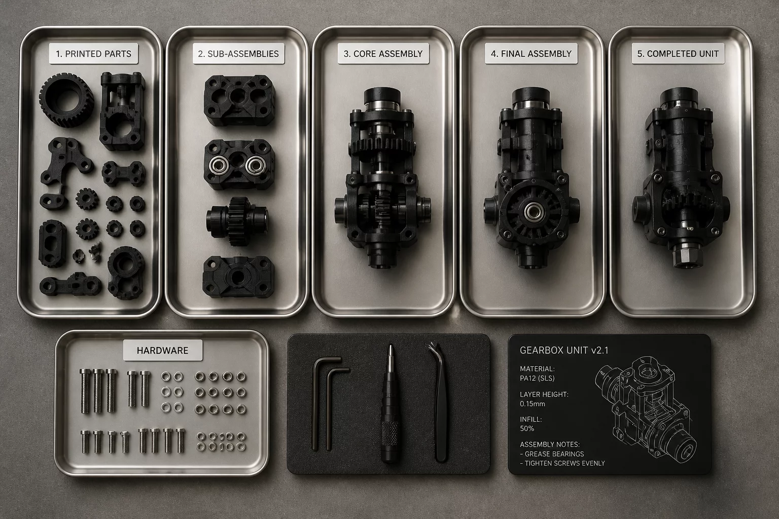
A disciplined CAD audit establishes operational boundaries prior to file conversion. By grouping components in the modeling environment according to mechanical sub-assemblies—such as lower structural chassis, internal drive carriages, wiring looms, and external covers—the print technician can translate CAD folders directly into dedicated build plates. This ensures that Stage 1 parts emerge from the first build ready for immediate bench assembly, hardware insertion, and threaded heat-set testing while subsequent plates continue manufacturing downstream components.
Multi-Part Slicing Strategies
Explore our in-depth guides on structural batching, plate isolation, and print farm scheduling.
Primary Failure Modes of Unplanned Plate Distribution
Throwing unverified assemblies into slicer queues introduces friction across physical production cells. When build allocations ignore mechanical sequence, engineering workshops encounter three persistent bottlenecks:
- Assembly bench starvation caused by structural baselines split arbitrarily across separate overnight printing batches.
- Intermingling high-wear friction latches with massive enclosure shells, forcing 14-hour reprints when a single fragile cantilever snaps.
- Hardware mismatch and fastener confusion resulting from unsegregated hardware bins and ambiguous part naming at checkout.
"A build plate is not merely a geometric arrangement of meshes; it is an executive contract between CAD architecture and workshop assembly cadence."
— Julian Vance, Principal Manufacturing Lead
Step-by-Step Cadence Mapping for Multi-Part Runs
Begin the audit by assigning an explicit assembly tier (Tier 0 through Tier 3) to every component in the CAD bill of materials. Tier 0 represents primary structural backbones and press-fit fastener cores. Tier 1 encompasses kinematics, gears, sliding rails, and retention clips. Tier 2 integrates electronics brackets, cable guides, and secondary housings. Tier 3 includes cosmetic faceplates, buttons, and decorative badges. Slicing these tiers as independent, sequentially named build plates guarantees that technicians can clear the first plate, install inserts, and verify kinematic fits without waiting for outer cosmetic parts to complete.
This staging framework also controls thermal risk and printer downtime. Structural components often demand higher chamber temperatures and prolonged cooling cycles in PETG or engineering filaments, whereas secondary housings can run rapidly in standard PLA or aesthetic compounds. Slicing with assembly stages in mind prevents inappropriate material compromises and protects overall workshop throughput.
Assembly Staging Inquiries
Auto-arrange maximizes packing density purely on bounding boxes, ignoring mechanical priority. It mixes base brackets with delicate bezels, meaning assembly cannot begin until the very last print job finishes, stalling downstream mechanical verification.
Most industrial enclosures and robotic prototypes benefit from three to four distinct stages: Core Structural Chassis (Stage 1), Internal Hardware and Kinematic Mounts (Stage 2), Wear and High-Tolerance Fasteners (Stage 3), and Cosmetic Enclosure Shells (Stage 4).
Use a prefix pattern like `ST01_ChassisCore_PETG.3mf` and `ST02_SlideRails_Nylon.3mf`. This immediately informs technicians which plate must run first and which raw filament spool must be loaded into the printer carousel.