Bridging Digital Slicer Plans and Physical Shop Floor Workflows
In busy additive fabrication workshops, the gap between what an engineer views in the slicer software and what a machine operator pulls from the print chamber remains a frequent source of costly errors. Subtle details like critical bed adhesion perimeters, specific layer-grain orientations for mechanical strength, and exact mating faces often vanish once files turn into autonomous G-code tasks. A standardized plate-role documentation sheet captures these nuances directly on a physical or digital job card, ensuring smooth operator handoffs across all production shifts.
Assigning a dedicated role to each build plate eliminates uncertainty across multi-part assemblies. Operators immediately know which plate carries primary cosmetic panels, which holds dense load-bearing brackets, and which groups delicate snap-fit clips requiring delicate post-print handling. This documentation framework transforms raw machine output into a streamlined assembly line where every technician knows precisely what to check before clearing the bed.
Explore Multi-Plate Project Structures
Review our foundational analysis on partitioning complex mechanical assemblies across dedicated print plates without overwhelming your workshop staff.
Crucial Details Floor Documentation Must Always Include
Inadequate handoff sheets lead to misidentified parts, mismatched filament spools, and stalled mechanical assemblies. High-efficiency production floors enforce documentation checklists that specify the following critical items:
- Exact spool identification codes, material flex ratings, and bed temperature targets to prevent unapproved generic filament substitutions.
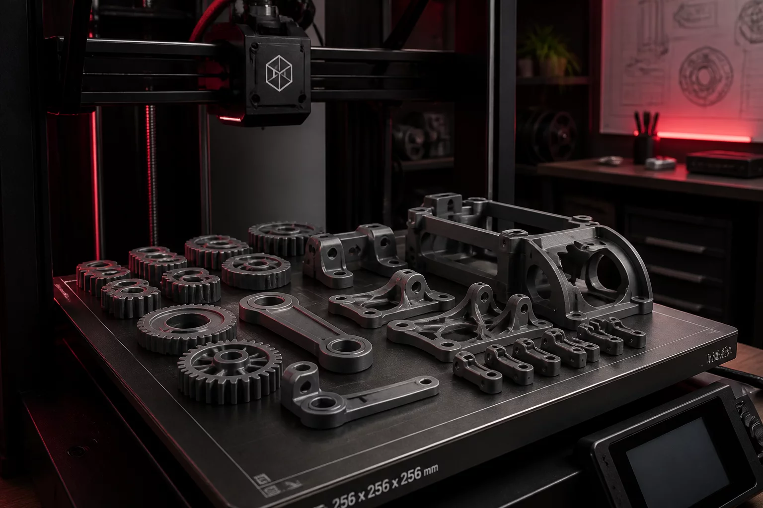
- Clear top-down plate layout previews illustrating part orientations, allowing technicians to spot detached support structures before bed clearing.
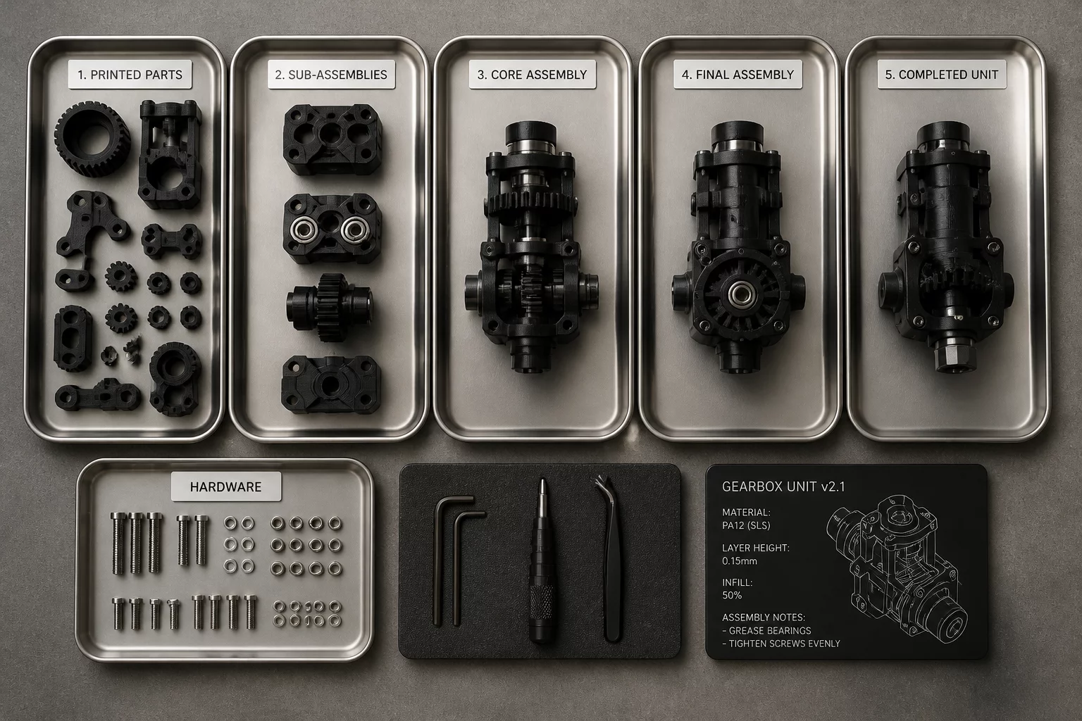
- Sequential hardware staging manifests specifying required M3 threaded inserts, dowel pins, and fasteners needed before parts move to assembly.
"A well-crafted plate handoff sheet enables any floor technician to inspect, clean, and bin multi-part builds with identical mechanical accuracy."
— Elena Rostova, Production Operations Lead
Setting Up Plate Verification and Component Bin Allocation
Effective workshop execution relies on linking each printed plate directly to an assigned post-processing tray. Once a build completes and the flex sheet cools, the operator checks finished components against the handoff diagram before detaching them. This visual verification confirms that thin cantilever arms and internal mounting bosses formed cleanly without delamination or missing geometry.
Immediately following deburring and support removal, parts move into color-coded component bins alongside pre-counted fasteners and hardware callouts. By integrating the plate-role card directly into bench sorting, downstream assembly technicians receive organized build kits ready for fastening, eliminating lost components and unnecessary production bottlenecks.
Frequently Asked Questions
The card must display the plate title, material type and color, nozzle size, bed surface requirements, estimated print duration, top-down part layout diagram, and matching hardware bin IDs.
Combining both formats yields the best reliability. Digital files stored in the shared cloud project ensure version control, while laminated cards placed directly on staging carts prevent confusion during bench deburring.
By indexing each component to its specific plate number and subsequent assembly bin, incoming technicians can immediately verify completed parts without consulting original CAD assemblies or slicer setups.