Why Material Roles Must Drive Plate Separation
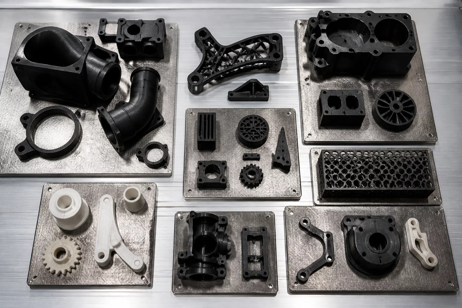
Slicing a multi-component device begins with categorizing parts by their operating duty cycles. An engineer often groups objects simply to fill build area without evaluating the physical function of each part. This practice creates severe inefficiencies when high-modulus structural ribs, compliant snap latches, and low-friction sliding faces share identical thermal environments.
Grouping components by physical roles protects layer integrity and chamber consistency. When parts demanding fiber reinforcement run on a dedicated plate, chamber temperatures remain uniform and extrusion paths maintain identical cooling speeds. Separating flexible gaskets and sacrificial slide bushings onto their own build surfaces prevents filament purge cycles and stops brittle polymers from being contaminated with residual elastomer resins.
Compare Stage Grouping With Material Isolation
Learn when to prioritize mechanical assembly sequence versus functional polymer separation in complex builds.
The Three Hidden Costs of Mixed-Duty Slicer Plates
Mixing parts with conflicting performance roles inside the same plate file forces compromises in chamber atmosphere, infill patterns, and nozzle travel parameters. Production runs configured this way experience predictable bottlenecks during quality control checks:
- Compromised layer adhesion caused by alternating layer fan speeds between delicate snap detents and heavy structural housings.
- Premature reprint triggers where a minor flaw on a decorative cap forces an operator to abort an entire tray containing critical mechanical gears.
- Excessive post-print sorting overhead resulting from operators manually separating components made from identical filament colors but differing infill geometries.
"Arranging components on build plates according to mechanical duty cycle rather than geometric volume eliminates 90% of reprint waste and ensures every part receives its optimal thermal envelope."
— Julian Vance, Lead Project Engineer
Operational Protocol for Multi-Plate Classification
Begin each slicing session by assigning every CAD body to one of four functional tiers: structural skeleton, sacrificial wear, environmental seal, or external cosmetic shell. Once classified, create distinct build plates in your slicer labeled with both the role designation and specific thermal recipe.
Assign dedicated plates for high-wear items such as pin hinges, drive dogs, and slide brackets. Because these parts wear down during field operation, having an isolated plate pre-configured with high-periphery perimeter walls and optimized seam alignments allows shop technicians to produce immediate replenishment kits without reloading whole assemblies.
Frequently Asked Questions
No. Even when printing an entire project with PETG, parts serving structural load roles require solid walls and low print acceleration, while cosmetic covers run faster with adaptive layer heights. Separating them by role preserves slicer settings without cumbersome per-object modifiers.
Grouping all parts of a given polymer class on a single plate ensures the heated bed stays at its target temperature through the entire job. Printers do not spend minutes ramping bed temperatures up and down between mixed parts during production shifts.
Use a clear prefix structure like [P1_STRUCTURAL_PA6CF], [P2_WEAR_POM], and [P3_SEALS_TPU]. This standard eliminates ambiguity about which bed sheet surface and nozzle setup the technician must install before launching the job.