Synchronizing Bed Cycles with Workshop Fastener Schedules
Organizing a multi-component mechanical build across three dedicated plates creates direct chronological alignment between printing completion and technician assembly steps. When print beds deliver components in the exact order required for chassis integration, sub-assembly fitting, and final enclosure closure, bench clutter disappears and technicians avoid idle waiting intervals between print completions.
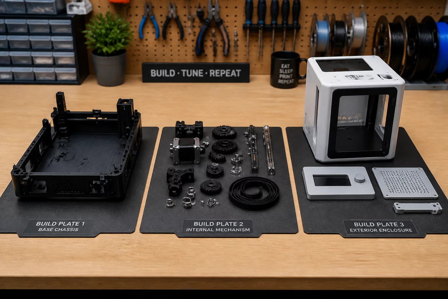
Three-Plate Functional Sequence Matrix
The following operational parameters demonstrate how components migrate from slicer build trays directly into staged assembly bins without sorting overhead.
| Parameter | Configured Value | Operational Guidance |
|---|---|---|
| Plate 1: Base & Skeletal Spine | Stage 01 Anchor | Prints the foundation chassis, motor anchor points, and primary heat-set brass insert bosses. |
| Plate 2: Internal Kinematics | Stage 02 Mechanism | Delivers planetary gearing, bearing sleeves, and structural linkages requiring immediate bench test fitting. |
| Plate 3: Enclosure & Fasteners | Stage 03 Outer Shell | Houses cosmetic bezels, snap lid covers, strain-relief clips, and external cable pass-throughs. |
| Print Stagger Cadence | 4.5h Target Interval | Calculated so assembly of Plate 1 finishes precisely as Plate 2 clears bed cool-down thresholds. |
| Post-Print Identification | Debossed Plate Labels | Every component contains an underside debossed marking P1, P2, or P3 for unmistakable operator sorting. |
Sequence Planning Fundamentals
- Hardware Alignment
- Threaded inserts and M3 hardware are pre-staged in bin 1 so installation begins the minute Plate 1 releases from the bed.
- Warping Risk Insulation
- Long structural rails remain on Plate 1 alone, preventing thermal draft changes caused by dense clusters of mixed geometry.
- Quality Verification Gates
- Dimensional tolerances on central shafts are verified before Plate 3 ever finishes, protecting production hours against assembly mismatch.
- Single Machine Continuity
- A single build chamber cycles through jobs sequentially without altering profile calibrations or bed temperatures between cycles.
Why Chronological Plate Layouts Protect Production
Packing parts into slicer plates by geometrical similarity often seems intuitive to digital CAD draftsmen. However, grouping five base housings together on one tray and all small covers on another forces assembly technicians to wait until every plate completes before turning a single screw. Organizing your slicer project into three sequence-dependent plates establishes a rhythmic assembly pipeline where fabrication and mechanical integration operate in parallel.
Executing Stage 1: Thermal Staking on Primary Frames
Plate 1 finishes printing first and supplies exclusively structural skeletal frames. While the 3D printer proceeds to Plate 2, the technician performs essential bench operations on the stable base unit without fighting workbench congestion:
- Thermal heat-set insert installation directly into dedicated foundation bosses.
- Press-fitting primary steel guide pins and motor mounting standoffs.
- Visual inspection of bottom-layer flatness against a granite inspection surface.
Executing Stage 2 and Stage 3: Drive Integration and Enclosure Sealing
By the time internal kinematics emerge from Plate 2, the skeletal core from Plate 1 is cooled, tapped, and ready for gear insertion. The technician drops in reduction gears, secures axial retaining washers, and runs functional manual rotation checks. When Plate 3 concludes its print schedule, the outer fascia, wire guards, and snap covers fasten directly over the verified mechanism, resulting in an unbroken assembly flow without sorting errors.
Frequently Asked Questions
Because plates are isolated by mechanical subsystem, only the internal kinematic plate requires restarting. Plate 1 chassis components remain valid and pre-staged on the bench, ensuring no re-printing of structural frames occurs.
Total nozzle extrusion time changes by less than 4% due to separate bed heating routines, but lead time from project inception to complete physical assembly drops by roughly 35% because assembly runs parallel to printing.
Organize parts trays into three labeled compartments: Bin 1 holds brass inserts and base bolts, Bin 2 holds pins and bearings, while Bin 3 holds exterior perimeter fasteners and rubber feet.
Optimize Your Workshop Slicing Sequences
Receive operational breakdowns, multi-plate build templates, and shop-floor staging checklists direct to your technical dispatch inbox.