Bridging the Gap Between Build Plates and Physical Bins
Multi-plate slicing files establish logical component hierarchies in software, yet workshops often dump freshly removed components into a collective pile. This post-print disconnect wastes valuable technician time as operators hunt for mating clips, specific brackets, and hardware fasteners across unstructured trays. Matching every digital plate index directly with an assigned color-coded bench bin preserves the assembly order established during the CAD preparation phase.
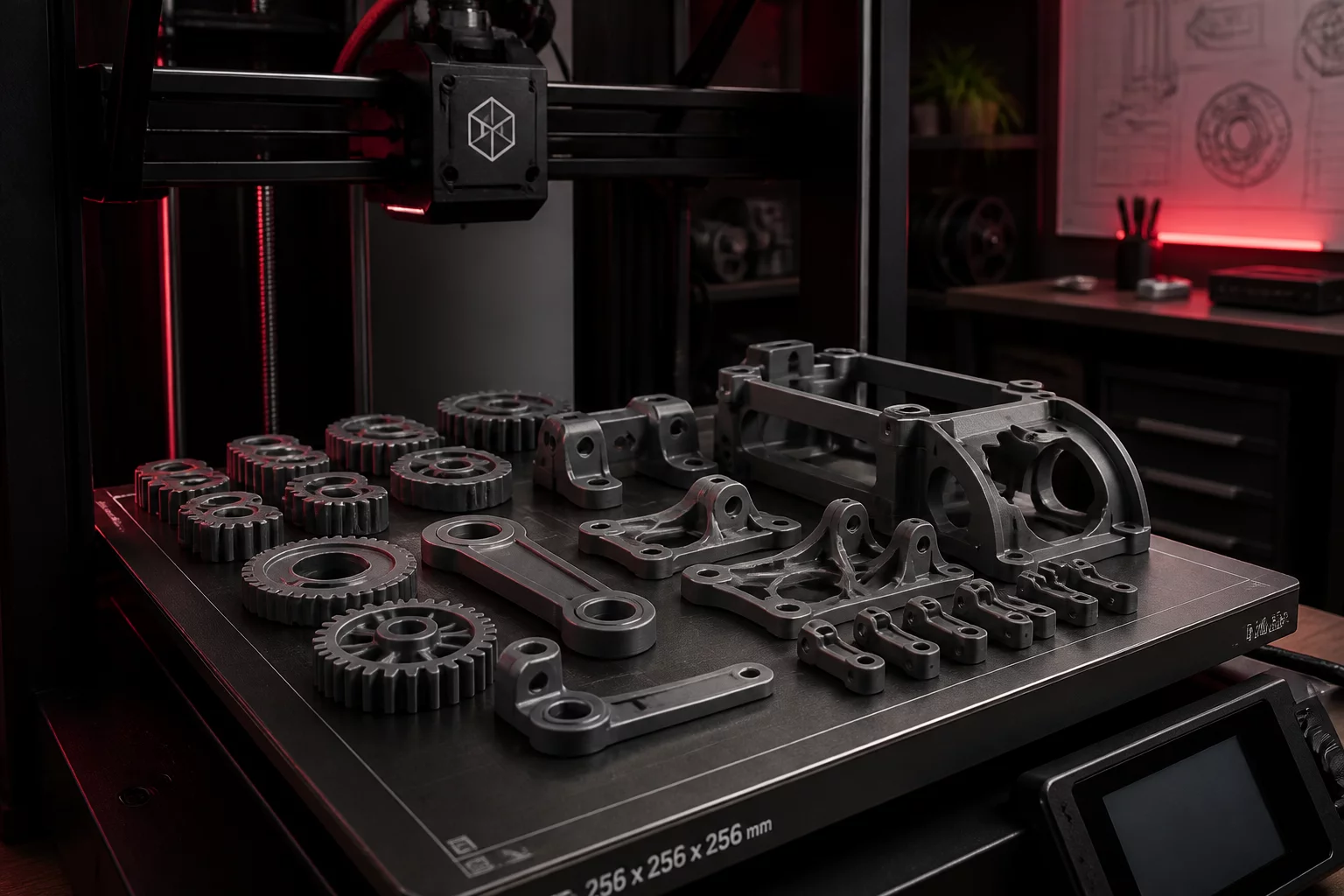
Technicians pull flexible steel sheets off the magnetic beds, pop the cooling components, and immediately deposit them into designated bin compartments labeled Plate 01, Plate 02, and Plate 03. This clean division keeps structural chassis pieces separate from delicate internal brackets and high-wear snap latches, avoiding mechanical scratches and premature intermingling before inspection.
Mastering Multi-Plate Digital Architecture
Discover how our digital plate management guides define clear grouping rules in Bambu Studio before parts reach the shopfloor.
Three Costly Hazards of Unstaged Print Offloading
Failing to implement physical staging immediately upon bed clearance causes silent productivity leaks across small-batch production lines:
- Symmetrical confusion: Inadvertently mixing left-hand and right-hand mirror brackets that have nearly identical silhouettes until final fastening fails.
- Tolerancing mix-ups: Blending prototype test fits printed at standard layer heights with fine-tolerance final units requiring distinct deburring.
- Displaced batch quantities: Miscounting fasteners and retention clips, leading to unnecessary reprinting jobs for parts that were merely buried under large chassis walls.
"If an operator cannot identify which slicer plate a printed component originated from within three seconds of picking it up, your staging architecture is broken."
— Julian Vance, Production Operations Lead
Executing the Workbench Bin Allocation Standard
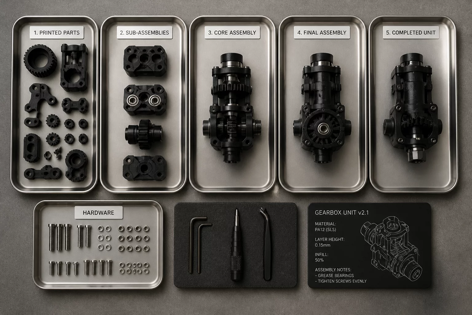
Standardizing bench staging requires setting up tiered stacking bins marked with plate numbering, stage responsibility, and required off-plate post-processing steps. Operators attach color tags indicating whether parts require support clearing, threaded brass insert installation, or solvent vapor smoothing before reaching the final assembly fixture. Staging bins keep mechanical fasteners like M3 machine screws and brass inserts nested directly alongside the corresponding 3D printed brackets.
When every build plate terminates in a dedicated bin holding both printed members and their mating hardware, final assembly runs seamlessly without searching for missing pieces. Slicer plate documentation transforms from an abstract slicer view into an actionable, repeatable hardware kit on your physical workbench.
Frequently Asked Questions
Hardware fasteners such as metric socket screws, threaded heat-set inserts, and dowel pins should be pre-kitted directly into micro-compartments within the staging bin assigned to that specific build plate. This ensures technicians immediately spot missing hardware before beginning mechanical assembly.
Standard ESD-safe euro-containers measuring 300x200mm or modular grid bins match typical 256x256mm build plate capacities perfectly. They allow comfortable part clearance without occupying unnecessary workbench surface area.
Parts should undergo rough support removal right beside the machine bed before entering staging bins. Final deburring, tapping, and heat-set insertion can then proceed in a controlled sequence directly from the designated bin.